


 Tel : +86-592-3926659
 Email : gilia@inthelaboratory.com
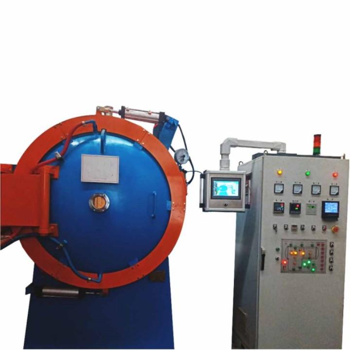
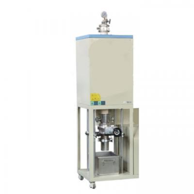
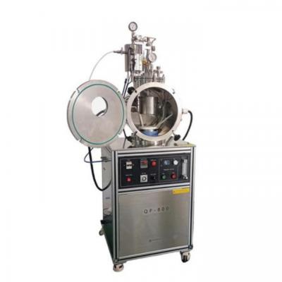
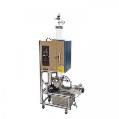
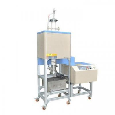
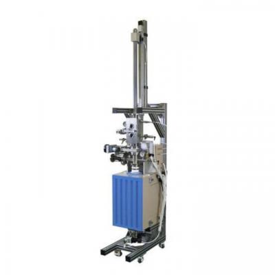
Lab Double Chambers Vacuum Oil Quenching Furnace

I. The main purpose
The FZC2-50 double-chamber vacuum oil quenching air-cooled furnace is a horizontal double-chamber cold-wall internal heating structure, electric heating, with two cooling methods, air cooling and oil quenching, and adopts a number of advanced proprietary technologies. And process parameters (temperature, vacuum degree, process time) are automatically controlled, with advanced technology, accurate control, high repeatability, strong anti-interference, long service life, and the user can call, edit and store process programs. With safety self-locking protection, fault self-diagnosis and alarm functions.
It can realize heat treatment processes such as vacuum oil quenching and vacuum air cooling. It is mainly used for vacuum heat treatment and vacuum post-weld heat treatment of heat-resistant steel, stainless steel and structural steel parts, and is used to eliminate the processing stress and use residuals of precision parts with finished dimensions. The stress stabilization treatment is used for precision forging and final heat treatment of precision forgings with finished dimensions. It can also be used for aging annealing, oil quenching, gas quenching, etc. of various materials such as high-speed steel, high-alloy tool and die steel, and precision machine parts. Heat treatment processes such as cold, after parts are heated, kept warm, and cooled under working vacuum, stainless steel, structural steel, etc. are bright and non-oxidized, and the surface of the parts does not increase carbon and reduce element depletion.
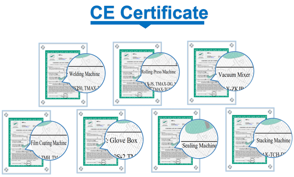
Standards: equipment design and manufacturing comply with ISO international standards;
The measurement units of all parts, components and various instruments of the equipment adopt the International Unit (SI) standard;
All parts, components and supporting systems of the equipment are designed and manufactured with domestic leading technology, which meets domestic general norms, safety and environmental standards;
All welds of the furnace body are 100% inspected, and after the processing is completed, water pressure, air pressure and helium mass spectrometer leak detector are used to detect micro leaks and other testing methods;
II. Technical specifications and parameters
|
2.1 Temperature parameter |
|
|
Model |
FZC2-50 |
|
Effective working area size (mm): |
350×350×350 |
|
Loading capacity (kg): |
70 Kg |
|
Heating power |
50kVA |
|
Maximum temperature |
1320℃ |
|
Operating temperature |
1250℃ |
|
Temperature control accuracy |
±1℃ |
|
Temperature uniformity |
≤±5℃(Temperature measurement at 5 points in working area, 500-1150℃, according to national standard) |
|
2.2 Vacuum parameters |
|
|
Ultimate vacuum |
≤4×10⁻¹Pa(Empty furnace, cold, clean) |
|
Working vacuum |
≤5 Pa |
|
Pressure rise rate |
≤0.67Pa/h |
|
Air cooling pressure |
<2 bar |
|
Vacuum pumping speed |
Pump from atmospheric pressure to 5 Pa≤20min |
|
Partial pressure range |
10Pa--200Pa |
|
|
|
|
|
|
|
|
|
|
|
|
|
|
|
|
|
|
|
|
|
|
|
|
|
|
|
|
|
|
|
|
|
|
|
|
|
|
|
|
|
|
|
|
|
|
|
|
III. Workmanship advantage
1. Flexible control mode, man-machine interface, stable operation
2. Intelligent and safe, green and environmentally friendly, no open flame, no oily smoke
3. Linkage and interlock protection alarm system, effectively protecting the safety of personnel and equipment
4. The heating elements are arranged in a 360°circular shape to ensure uniform heating and improve heating efficiency
5. The unique design of oil cooling system and low pressure air cooling system ensures the uniformity and rapidity of cooling, and greatly reduces the deformation of the workpiece.
IV. Brief introduction of equipment structure
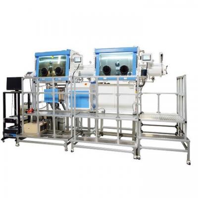
The FZC2-50 vacuum furnace is a horizontal double-chamber structure, and its main body is a double-layer water-cooled structure. It is composed of a furnace body, a vacuum system, an electric control system, a gas charging system, a water cooling system, a pneumatic system, and an out-of-furnace charging car.
1 Furnace part
The furnace body of the vacuum furnace is a horizontal, double-chamber structure. The front chamber of the furnace body is a cooling chamber, the middle is a gate valve with vacuum sealing and heat insulation, and the rear chamber is a heating chamber. The furnace body is the main part of the vacuum furnace, which is composed of the furnace body and the furnace door.
The furnace body is welded from a high-quality carbon steel plate reel. There is a gap between the two layers, cooling water is passed through, and the two ends are welded to flanges. The side wall of the furnace body is equipped with a vacuum system interface, a water-cooled electrode interface, and a thermocouple. Devices such as interface, cooling pipe interface, inflation system interface, safety valve interface, opening of lifting mechanism, opening of oil stirring, opening of feeding and discharging mechanism, etc.
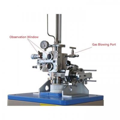
The furnace door is welded by a double-layer elliptical head and a round flange, with an observation hole in the middle. The furnace door and the furnace body are connected by hinges. The temperature-resistant rubber sealing ring is used between the furnace body flange and the furnace door flange. The furnace door compression mechanism adopts a two-way lock ring compression method (cylinder drive) and automatic locking. At the same time, it is equipped with detection devices such as travel switch and pressure detection, which can ensure that the furnace door cannot be opened when the furnace is inflated. Using this compaction method can meet the sealing needs of the furnace during vacuuming and charging air cooling.
The equipment has multiple over-pressure protection, and the furnace body is equipped with a safety valve, an electric contact pressure gauge, and a pressure sensor. During use, when the working pressure is reached, the inflation system will automatically shut down, and when the pressure is low, the system will automatically replenish air. The system overpressure protection can be set in the electric contact pressure gauge and the pressure sensor at the same time to achieve double protection. When the charging pressure reaches a certain pressure, the safety valve on the furnace body will automatically open, so as to ensure the safety of the equipment.
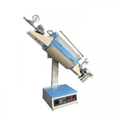
1.1 Heating chamber
The heating chamber is placed in the vacuum furnace and is composed of heat shield, heating element, material table and supporting porcelain seat.
1.1.1 The heat shield is composed of a metal frame and graphite soft felt. The metal frame adopts an integral cylindrical structure, which is welded by ribs and perforated steel plates, which is sturdy and durable; the insulation layer is composed of multiple layers of graphite soft felt, and the insulation layer is fixed on the stainless steel chamber frame with graphite rope;
1.1.2 The heating elements are graphite tubes, graphite connecting plates, and graphite nuts, which are evenly arranged along the circumference of the inner wall of the insulation layer. The furnace temperature is uniform and easy to replace. Use suspended electrodes to support and fix the heating tube, and protect the electrodes to reduce carbon black deposition;
1.1.3 The material table is composed of graphite rod pillars, graphite hearths and AL2O3 spacers on the hearth (high-quality ceramic parts with high temperature resistance are selected to ensure that the heating body has good insulation performance) to prevent the material pan and graphite at high temperatures. Bonding of the hearth;
1.2 Cooling chamber
The front chamber of the vacuum furnace is a cooling chamber, which can be oil quenched and air cooled. The upper part is an air-cooled room, equipped with an air-cooling system; the lower part is an oil quenching chamber, equipped with a lifting mechanism, a feeding and discharging mechanism, an oil stirring device and an oil heating device.
1.2.1 The air cooling system is located in the upper part of the cooling chamber and consists of a high-speed fan, an impeller, a heat exchanger and a flow guide device. When air-cooling, fill in inert gas such as high-purity nitrogen or high-purity argon to form a forced convection cycle under the drive of a fan to achieve rapid air-cooling of the workpiece (the air-cooling pressure can be arbitrarily selected within the range of 0.8-2bar). The cooling fan device is fixed on the furnace body by a flange, which is convenient for overall disassembly and maintenance, and is equipped with an overpressure exhaust valve to ensure safety;
1.2.2 Lifting mechanism: Driven by a motor + frequency converter, the lifting and lowering cart is driven by a screw and nut mechanism. The lift truck has three speeds, slow speed when feeding and reclaiming, slow start, fast oil in and slow in position when oil quenching;
1.2.3 Feeding and discharging mechanism: the chain in the furnace is driven by the motor-driven sprocket, and the chain with the tensioning mechanism is equipped with a shift lever to drive the feeding trolley in and out;
1.2.4 Oil stirring system: The agitator in the oil tank is driven by the motor controlled by the frequency converter, and the deflector can promote the reasonable circulation of the vacuum quenching oil and improve the cooling capacity of the quenching oil. The agitator adopts propeller-shaped double impellers, with low noise and high efficiency.
1.2.5 Oil heating device: The system is composed of a temperature detection system and cooling and heating devices. Through the oil temperature detection system and the set value of the oil temperature, the oil cooler or heater is connected in time to control the oil temperature of the quenching oil.
1.3 Middle door
3.1.3.1 In the middle of the two rooms is an insulated door and lock box, cooling water is passed through the wall in the middle, and a high-temperature-resistant sealing ring is installed. The sealing ring is not bake by the high temperature of the heating chamber along with the movement of the valve plate, so it has a long service life and is easy to replace at the same time.
3.1.3.2 The plug-in plate intermediate gate valve is a composite structure of heat insulation and sealing. The valve is composed of a valve body, a heat insulation layer, a four-bar linkage mechanism, an air cylinder, and a guide rail. Since there are no water-cooling and sealing parts on the valve body, there are no movable water-cooling pipe fittings, which basically eliminates the hidden trouble of failure. The mechanism runs smoothly during the rising or falling action of the heat insulation door, which is safe and reliable, and has strong stability.
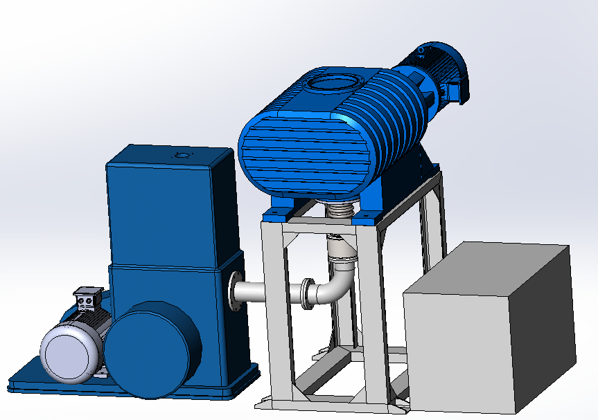
2.Vacuum system
The vacuum system consists of a vacuum unit, a vacuum baffle valve and other vacuum measuring components.
● Vacuum unit: consists of 1 ZJ-500 Roots pump and 1 2X-70 rotary vane pump;
● The vacuum measurement system is composed of ZDZ-52T resistance vacuum gauge and gauge, with vacuum control point setting. It has multiple functions such as setting control, data output, fault alarm, etc.; Ø
● The vacuum system has a self-protection logic interlock system to avoid misoperation;
● In the event of a power failure, all vacuum valves will be automatically closed instantly to ensure the vacuum in the furnace and prevent oxidation of the furnace bladder and workpiece;
●Install a silencer at the vent to reduce noise in the workshop;
●Install a fume purification device at the outlet of the rotary vane pump, which can filter the gas in the vacuum furnace and discharge it to avoid pollution in the workshop.
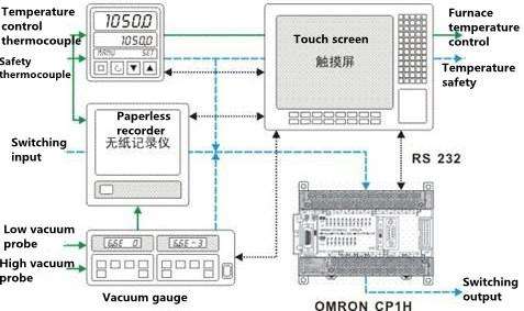
3 Electric control system
The system consists of two parts: a temperature programmable control system composed of touch screen, thyristor voltage regulator, and programmable controller, and a mechanical action programmable control system composed of PLC. It can realize automatic program operation and also has manual operation. Function.
3.1 The voltage regulator adopts a high-current, low-voltage power supply mode to cooperate with a PID temperature control instrument to achieve continuous temperature adjustment.
3.2 The temperature controller adopts the FP33 intelligent temperature controller with a temperature control accuracy of ±0.1% F.S. It can store 9 process curves, each with 20 segments, multiple groups of PID parameters, and has a PID parameter self-tuning function.
3.3 Use CP1E programmable controller (Omron) to control mechanical actions, which can realize all automatic control of pumping out and opening valves.
3.4 Adopt Pangu (0~1300℃±0.5%) paperless recorder, which can record temperature curve and vacuum curve continuously.
3.5 The temperature measuring element adopts double core S couple (platinum rhodium 10-platinum), one core is used for temperature control, and the other is used for recording and alarming.
3.6 Touch screen control system
*The operating system is easy to learn and use; the friendly graphical man-machine control interface can dynamically display the process and movement status in real time.
* Fully digital monitoring of temperature, vacuum and other data information, and data storage, curve recording, etc. can be performed at the same time.
* Mass storage space and great expansion potential, multiple operation permissions, each operation permission is protected by a password.
*The record includes the following:
Process records: heating temperature, time, vacuum degree and air cooling pressure;
Production records: production batch number, comprehensive card number, material grade;
Operation record: operator name, operation time; fault record;
*It is equipped with simple fault self-diagnosis function, which can display the fault source in time and has sound and light alarm and self-protection functions, so that the operation is simple, easy to learn, and easy to use, so that the operator can quickly become familiar with the use and maintenance of the equipment.
4 Inflation system
In order to meet the gas (inert gas) needs in the equipment process, the equipment is equipped with a gas filling system, which is composed of gas source (user-prepared), gas collecting pipeline, fast filling system, micro filling system, pressure detection system, etc. Auxiliary cooling of the air in the furnace can be realized.
●The gas collection pipeline is composed of a high-pressure hose and a manual switch, which is directly connected to the gas source.
● The fast charging system uses a large-diameter pneumatic charging valve to complete the rapid charging of the vacuum furnace. In the case of rapid cooling, inflate to 0.6bar before starting the fan, and then charge to the set pressure when the fan is running normally. The air cooling pressure is adjustable from 0.6 to 2 bar.
● The partial pressure system is composed of manual shut-off valve, solenoid valve, fine-tuning valve, etc. During the heating process, this system and the vacuum gauge can be used to regulate and control the partial pressure of the vacuum in the furnace.
● Equipped with a backup manual inflation interface for power failure to protect the equipment in case of an emergency power failure.
5 water cooling system
This equipment adopts a closed circulating water system, which cools each part of the equipment (furnace body, furnace door, vacuum unit, air-cooled motor, heat exchanger, water-cooled electrode, etc.) from the main water inlet pipe through each branch.
* The system consists of stainless steel globe valve, electric contact pressure gauge, galvanized pipeline, water flow observation mirror, etc.;
* The cooling water inlet is equipped with a water pressure sensor and an alarm protection device. When there are abnormal conditions such as water cut, underpressure, overpressure, etc., the heating can be cut off in time and an alarm;
* The sound and light alarm can be activated when the water pressure is under-pressure, and when no one cancels the under-pressure alarm, the equipment will automatically close all parts associated with the under-voltage in the order of operation;
* Acoustic and visual alarm for overpressure can be activated when the water pressure is too high. When the water pressure reaches a certain value, the safety valve acts to release the water pressure to protect the equipment from damage;
* Equipped with a spare cooling water interface, which is connected to emergency water pipelines such as urban tap water or workshop high temperature water tanks. When there is a power failure in the workshop, the emergency water pipeline is automatically opened to protect the equipment.
6 Pneumatic system
It is composed of pneumatic triple parts (dewaterer, pressure gauge, oil mist device), electromagnetic reversing valve and pipeline. It can provide clean compressed air to pneumatic actuators (such as cylinders, inflation valves, vacuum valves, etc.). The actuators are reliable in action, and the pipeline is neat and beautiful.
7 Furnace Outer Material Car
The material car outside the furnace adopts the manual aligning universal type, which is convenient and saves space. It can be conveniently docked with the running rail in the furnace to realize the transfer of the workpiece inside and outside the furnace. There is a vacuum quenching oil collector on the material car outside the furnace to prevent pollution of the work site.
V. Main configuration list
|
Serial number |
Name |
Factory |
Model |
|
1 |
Rotary vane pump |
Zhejiang Xinjiali Company |
2X-70 |
|
2 |
Roots pump |
Zhejiang Xinjiali Company |
ZJP-500 |
|
3 |
Thyristor voltage regulator |
Jiangsu East Technology |
|
|
4 |
FP33 temperature control table |
Shimaden co., ltd. |
FP33 |
|
5 |
Cold room pressure controller |
British WEST Company |
P4100 |
|
6 |
Programmable control |
Omron Corporation |
|
|
7 |
Paperless recorder |
Hangzhou Pangu Company |
|
|
8 |
Digital display vacuum gauge and supporting regulation |
Chengdu Ruibao Company |
|
|
9 |
Industrial touch screen |
Kunlun General State |
|
|
10 |
Pneumatic Components |
AirTAC |
|
|
11 |
Inflation valve |
Shenyang |
|
|
12 |
Electromagnetic pressure difference valve |
Shenyang |
|
|
13 |
High pressure fan |
Kaifeng Shengda |
|
|
14 |
High efficiency heat exchanger |
Xuzhou Jiangsu |
|
|
15 |
Platinum rhodium dual core thermocouple |
Chongqing Dazheng |
Double core S couple cou |
|
16 |
Main electrical components (air switch contactor, etc.) |
Schneider |
|
VI. Goods supplied in sets
6.1 Complete supply main body
Vacuum furnace main body ······· 1 set
Vacuum unit ········· 1 set
Electric control cabinet ·········· 1 set
Voltage regulator ·········· 1 unit
Out-of-furnace charging car ········· 1 set
Flue gas purification device········1 set
Vacuum gauge·········· 2
6.2 Spare parts and accompanying tools
Seals··········· 1/2 unit
Insulator··········· 1/2 unit
Heating element·········· 1/2 unit
Random tools·········· 1 set
6.3 Random technical documents
Equipment Technical Manual········· 2 copies
Layout plan and foundation plan········· 2 copies
Electrical schematic diagram, vacuum system diagram······· 2 copies
Water cooling system diagram, pneumatic system diagram······· 2 copies
Inflation system diagram, vulnerable parts diagram ········2 copies
Main accessory manual ··········1 copy
Product delivery certificate············1 copy
VII. Conditions that the demand side should have on site
* Supply of basic facilities (electricity, water, nitrogen, compressed air, etc.); provide auxiliary tools required for equipment installation and commissioning.
* Basic transportation loading and unloading equipment, used for the loading and unloading of the equipment and transportation to the final installation factory of the equipment.
* Basic civil engineering, suitable plant (height, site, crane).
* Workshop foundation, embedded pipelines, etc. (including cover plates, etc.);
* Supply, connection and installation of various pipelines to the furnace body;
* Power supply (AC380V, three-phase, 50Hz) and the connecting cables connected to the equipment voltage regulator and the control cabinet;
* Total water supply (inlet water pressure: 0.2~0.25MPa; inlet water temperature: 10~32℃; water quality: hardness <10 degrees, solid content <250mg/L) and the connecting pipes and valves of the main drainage pipe and the equipment;
* The pipeline between the inflation system and the high-purity nitrogen (99.999%) gas source;
* Compressed air source (gas pressure 0.4~0.6MPa, self-purchasing a small air compressor with a gas output of 0.6m3/min) and pipelines;
* Exhaust gas pipeline of vacuum pump group;
* Tooling;
* On-site workpiece handling.
*The cooling water can cause the equipment to fail to work normally due to various types of sediments, biological decay and erosion. In order to extend the service life of equipment and piping systems, prevent chemical erosion and calcification, and reduce operating costs, the quality of cooling water should meet the following requirements:
1) PH value: 7.0~8.0
2) Suspended solids 50meq/l
3) Carbonate hardness: 2.14~3.56meq/l (without the participation of phosphate or stabilizer)
4) Non-hydrochloride hardness: 18meq/l
5) Choose appropriate scale and corrosion inhibitors
6) Use appropriate insecticides to inhibit algae.
VIII. Installation, debugging and acceptance
1 Within 50 days after the contract takes effect (after the advance payment is in place), the supplier shall provide the purchaser with the layout plan and foundation plan of the equipment, and the purchaser shall carry out the construction according to the plan;
2 Before the equipment is shipped, the supplier shall first carry out the internal inspection and acceptance of the equipment, and after the completion, the supplier will notify the buyer to the production site for pre-acceptance; at the same time, confirm all purchased parts and electronic control systems item by item according to the technical agreement; the pre-acceptance is qualified After that, the representatives of the supplier and the demander can sign the "Pre-acceptance Report" according to the inspection results before the goods can be shipped;
The pre-acceptance content includes:
* Basic inspection (cold test): the whole equipment is arranged reasonably; the inspection of purchased parts (the packing list and serial number of the motor, sensor, cylinder, electrical components and imported equipment); correct wiring.
* Dynamic performance testing: the smoothness of mechanical device action; testing gas circuit under pressure; testing interlock and alarm system.
3 After the equipment is delivered to the buyer's site, the buyer is responsible for unloading and hoisting. The installation of the entire production line will be completed by technical personnel with the cooperation of the buyer's staff. The engineer will check whether the wiring and connections are correct, make the equipment run, and give operating instructions to the operators.
After the equipment installation and commissioning are completed in the buyer's factory, the final acceptance of the entire equipment will then be carried out.
IX. Safety protection measures and performance
1 The equipment is equipped with usual safety devices with interlock protection function to avoid equipment failures caused by misoperation and production accidents, but the supply of compressed air and cooling water must be guaranteed.
2 In the case of non-power failure, the control system will send out sound and light alarm signals when various abnormal states or failures occur in the equipment, and automatically record the type of alarm and the time of the alarm.
3 Safety measures during heating
* Safety under vacuum or partial pressure: If the degree of vacuum or partial pressure does not reach the set value, suspend heating. The heating program remains in the "HOLD" state. After the vacuum degree or partial pressure reaches the set value, the heating program automatically resumes and continues to execute.
* Cooling system protection: the water inlet and outlet of the closed cooling system are equipped with temperature, pressure, and flow safety alarm functions;
* Safety measures for compressed air: If the pressure of compressed air is lower than 5 bar, a sound and light alarm will be activated, and the heating will be stopped manually or automatically according to the setting of the program.
* Overpressure protection: The equipment is equipped with a safety valve and a manual vent valve. When the actual inflation pressure of the equipment is greater than the set value, a related alarm will be issued. If someone finds out in time, the manual vent valve can be opened to decompress the equipment, if no one finds it. The sound and light alarm fails, and the safety valve can be opened automatically to protect the equipment from production safety accidents;
* Safety measures for cooling water: if the inlet pressure of the cooling water is lower than 1 bar (the pressure can be set), an audible and visual alarm, according to the setting of the program, manually or automatically stop heating; if the preset inlet temperature of the cooling water Over 35 ℃ (this temperature can be set), sound and light alarm, according to the setting of the program, manually or automatically stop heating.
* Overheating protection: When the heating temperature exceeds 1250 ℃ (this temperature can be set) due to a malfunction, the heating will be stopped.
* Safety measures for sudden power failure: the vacuum valve and the gas valve will automatically close. The valve on the waterway opens automatically. The furnace is still under vacuum or atmosphere protection. When the call is received again, the heat treatment process will continue to be executed manually.
4 Safety measures for furnace body
The automatic locking mechanism of the furnace door is equipped with a safety switch to monitor whether its position is correct; if the gas pressure in the furnace and the outdoor pressure are unbalanced, the furnace door cannot be opened.
5 This equipment is convenient to use and maintain, safe and reliable, economical and reasonable, practical and beautiful; the materials for the furnace are carefully selected and meet the requirements of relevant standards;
6 All heated mechanical parts and metal structure parts of the furnace will not cause jamming, seizure or other failures due to thermal expansion, ablation, oxidation, creep, etc.;
7 The equipment has a grounding device. The grounding device should be located at a location convenient for wiring, and it should be in good contact with the furnace shell or furnace frame and have a grounding mark. The grounding device can connect wires that are not less than 50% of the power cord cross-section; the exposed live parts of the furnace, as well as gears, belts, chain drives and other parts have protective covers or corresponding protective measures;
8 The cooling water system and gas circuit system of the furnace meet the requirements of normal use, and there is no leakage during work;
9 The vacuum furnace body, pipes, etc. have good airtightness, and are convenient for leak detection and repair welding; conductive joints, thermocouple export devices, vacuum gauge pipes and vacuum pressure gauge joints, etc. all adopt vacuum sealing structure; the vacuum pump set has high efficiency, Safe, durable and reliable and low failure rate;
|
|
|
|
|
|
|
|
|
|
|
|
|
|
|
|
|
|
|
|
|
|
|
|
|
|
|
|
|
|
|
|
|
|
|
|
|
|
|
|
|
|
|
|
|
|
|
|


 IPv6 network supported