


 Tel : +86-592-3926659
 Email : gilia@inthelaboratory.com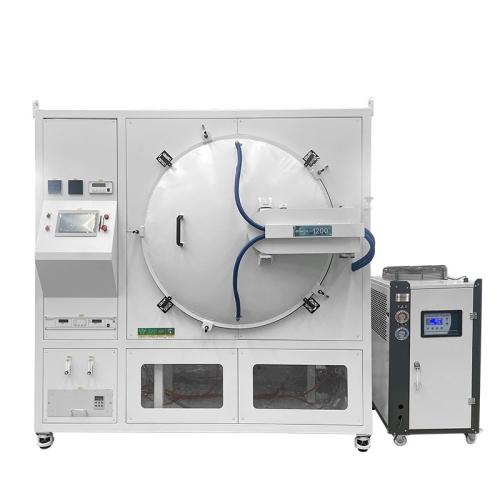
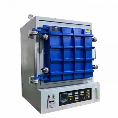
1200C Vertical Atmosphere Furnace for Vacuum Sintering of Alloy Materials or Non-metallic Materials
1. Overview
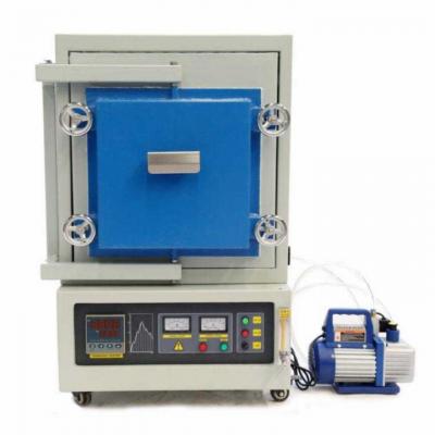
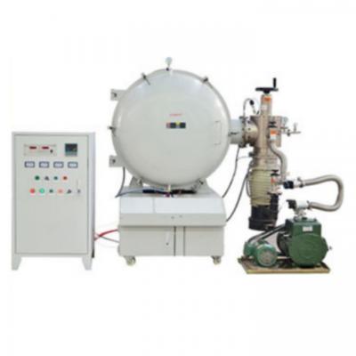
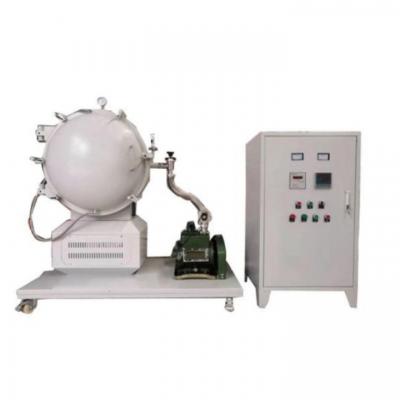
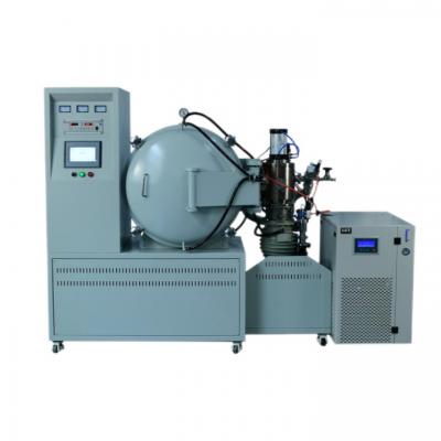
The GWDL-VSF 1200℃ high-temperature vertical vacuum atmosphere sintering furnace is mainly used for vacuum sintering of alloy materials or non-metallic materials.
The complete equipment consists of a vertical main unit (single chamber), vacuum system, gas filling system, water cooling system, electrical control system, etc.
2. Main Technical Parameters
|
Specification |
Parameter |
|
Furnace Chamber Dimensions |
500 × 500 × 500 mm |
|
Vacuum Degree |
6.67×10⁻³ Pa |
|
Pressure Rise Rate (empty furnace, cold) |
≤0.66 Pa/h (calculated based on 24-hour pressure holding) |
|
Pumping Speed (at 1×10⁻³ Pa, room temperature, empty furnace, with main valve open) |
≤120 min |
|
Maximum Design Temperature |
1200℃ |
|
Continuous Operating Temperature |
1150℃ |
|
Heating Rate |
≤10℃/min (non-linear) |
|
Temperature Uniformity |
≤±5℃ (tested at 1200℃ with nine points under no-load condition) |
|
Temperature Control Accuracy |
±1℃ |
|
Compatible Atmospheres |
Nitrogen, argon, carbon monoxide, oxygen, hydrogen, etc. |
|
Oxygen Content Analyzer |
Real-time monitoring of residual oxygen content in the furnace to ensure a stable low-oxygen environment, thereby avoiding material oxidation and performance degradation. |
3. Standard Structure and Features
3.1 Vacuum Furnace Main Unit
The vacuum furnace main unit has a vertical single-chamber structure, consisting of the furnace body, furnace door, furnace stand, heating chamber, etc.
3.1.1 Furnace Body and Furnace Door
The vacuum furnace body sits on the furnace stand. Both the furnace body and the furnace door have double-wall water-cooled construction.
The inner walls of the furnace body and door are made of carbon steel (welded), and the outer layer is a protective shell.
The furnace body is CNC machined and finished through polishing, grinding, pickling, phosphating, powder coating, high-temperature baking, etc. Two-tone color scheme – aesthetically pleasing.
Features anti-oxidation, acid/alkali resistance, corrosion resistance, high temperature resistance, and easy cleaning.
The furnace chamber steel plate thickness is 6–20 mm, welded on both sides, and can withstand a positive pressure of 0.1 MPa.
Furnace outer shell temperature: ≤45℃ under continuous operation.
Port configuration:
Top cover center: one ½" NPT female port (reserved)
Furnace door center: one ½" NPT female port (reserved)
Upper part of furnace body: two ½" NPT female ports for inert gas inlet
Top and bottom of heating chamber: one ½" NPT female port each for thermocouple installation
Furnace door structure:
The furnace door is side-opening with pneumatic locking.
3.1.2 Heating Chamber, Heating Elements and Insulation Components
Furnace lining structure:
Made of vacuum-formed alumina lightweight material.
Load-bearing or impact-prone areas (furnace opening, furnace bottom) use lightweight hollow-sphere alumina board.
Features: high service temperature, low heat storage, excellent thermal shock resistance – no cracking, no spalling, good insulation.
Insulation material – three-layer structure:
Inner layer: 99% lightweight alumina material
Middle layer: alumina fiber board
Outer layer: ceramic fiber board
Heating elements:
Silicon carbide rods
3.2 Vacuum System and Vacuum Gauge
The vacuum system consists of a mechanical pump, diffusion pump, pneumatic baffle valve, connectors, gauge tubes and auxiliary devices.
Configuration: one mechanical pump, one diffusion pump.
Vacuum gauge: one digital resistance vacuum gauge.
Operation: automatic programs can be set via the touch screen, including automatic furnace purging, gas switching, vacuum pumping, etc.
3.3 Water Cooling System
Consists of stainless steel stop valves, water inlet, drain tank, water pressure electric contact pressure gauge, etc.
One chiller is supplied with the furnace.
The drain pipe is equipped with an over-pressure protection device.
In case of water supply failure, audible/visual alarms and interlock functions are activated, with automatic switchover to emergency cooling water.
3.4 Gas Filling System
Consists of gas filling stop valves, gas manifold, solenoid valves, vacuum electric contact pressure gauge, etc.
Allows adjustment and control of the vacuum level inside the furnace during heating.
The piping is equipped with a mass flow meter for manual measurement and control of gas flow.
3.5 Pneumatic System
Consists of pneumatic valves, solenoid valves, oil-water separator, oil mister, pressure gauge, etc.
The user only needs to connect the pneumatic interface to a compressed air source.
3.6 Electrical Control System
The electrical control system consists of SCR voltage regulators, intelligent instruments (for temperature program control) and PLC (for mechanical action control). It provides the following functions:
Programmable temperature control
Temperature chart recording
Vacuum degree chart recording
Alarm and interlock protection for water pressure, over-temperature, over-current, etc.
Automatic/manual operation switching
3.6.1 Temperature Control Instrument
Uses Yudian temperature controller. Control accuracy: ±1℃.
3.6.2 Temperature and Vacuum Recording Instruments
Uses touch screen for display and recording.
3.6.3 Temperature Measuring Thermocouples
Equipped with K-type thermocouples for temperature control, recording and over-temperature alarm.
Includes one control channel and one measurement channel.
3.6.4 Programmable Logic Controller (PLC)
Controls logic including vacuum pumping, valve interlocking, heating control and various alarms.
Model: Siemens S7-200 CPU + expansion module.
Electrical panel reserves 20% spare space; 30 cm expansion space is reserved to the right of the S7-200.
3.6.5 Analog Monitoring and Protection System
The control cabinet is equipped with a mimic diagram that visually displays the operating status of the vacuum furnace.
Features fault self-diagnosis (water failure, vacuum pump overload, over-temperature, over-current, over-pressure, etc.).
Complete audible/visual alarm and interlock protection system.
3.7 Pressure Protection System
To prevent danger caused by closed exhaust port, blocked exhaust port or excessive furnace pressure, a pressure protection system is provided.
Principle:
Signal from electric contact pressure gauge or pressure sensor → control module closes the solenoid inlet valve → activates solenoid exhaust valve and alarm → releases internal pressure and issues audible/visual alarm, thereby ensuring safe equipment operation.
4. Utility Requirements
4.1 Power Supply
Power supply: 380V, three-phase, 50Hz
Power: 250 kVA
4.2 Water Supply
Inlet water pressure: 0.2–0.3 MPa
Inlet water temperature: ≤32℃
Water consumption: 10 m³/h
4.3 Compressed Air
Pressure requirement: 0.4–0.5 MPa
4.4 Inert Gas
Type: Nitrogen, argon or hydrogen
Purity: 99.99–99.9995%







 IPv6 network supported